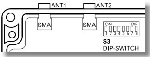
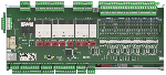
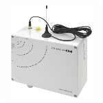
The deployed radio component is defect! The receiver module is no longer able to communicate with the radio sensors, see grapgic arrangement of the antenna sockets.
Every device is fitted with a second antenna module which can be switched to temporarily. In order to do this
1.) Switch device to zero potential
2.) Screw the antenna to ANT2 (inner socket, i.e. P20)
3.) Set DIP switch 1 to ON
4.) Switch the device back on
?In order to switch back to component 1 (in the event that e.g. component 2 was used from the beginning)
1.) Switch device to zero potential
2.) Screw the antenna to ANT1 (outer socket, i.e. P19)
3.) Set DIP switch 1 to OFF
4.) Switch the device back on
WARNING: Following switching of the components it must be checked to see whether radio contact can now be established!