Speichern
Abbrechen
Upper/lower case is ignored
Phrase search: "search this phrase"
Placeholder for one token: Techno?ogy
Placeholder for multiple tokens: EXC*
Logical operators: AND OR ....
Exclusion: cnc -tools
Defined distance: "cnc steuerung"~5
Register
Login
Deutsch
English
Français
Favorites
...
Machine Automation
Refrigeration and Building Management Systems
/
E*LDS System
Virtus Caelum Apps
Virtus Tectum Grid
System Centre & Operator Terminal
Pack Controllers
Temperature displays &
Operator interfaces
Building Management Systems
PC Software LDSWin
Receiver Module & Wireless Sensors
Gateways
Electrotechnical design
FAQ E*LDS
E*LDS explains itself
LDSWeb
E*LDS
Training
E°EDP offline archive
Discontinued Products
Case Controllers
/
Virtus LINE VCC 500
UA 213 S SemiPlugin
UA 30 Family
DISCONTINUED - UA 300 Family
UA 400 Family
/
UA 400
UA 410 D
UA 410 L
UA 412 S / UA 413 S
CE conformity declaration UA 400 Family
UA 400 E / UA 401 E / UA 410 E
/
Accessories Case Controller
FAQ Case Controllers ..
Usefull helper case controller
Temperature displays &
Operator interfaces
CAN bus
E*COP+ Saugdruck-Optimierung
Product photos UA 400 Family
Firmware UA 400 E / UA 401 E / UA 410 E
/
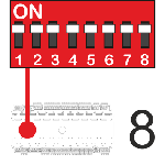
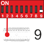
2nd Generation - DIP switch 9x
1st Generation - DIP switch 8x
/
Release notes UA 400 E / UA 410 E V2.07
Case controller has not been detected in Windows
UA 400 E / UA 410 E Operating instruction - V2.00
Versioning
Replace
UA 400 E / UA 410 E Operating instruction - V2.00
(P. 223/304)
More information
UA 400 E / UA 410 E Operating instruction - V2.00
(P. 223/304)
More information
UA 400 E / UA 410 E Operating instruction - V2.00
(P. 223/304)
More information
Info
1
2
3
4
5
6
7
8
9
10
11
12
13
14
15
16
17
18
19
20
21
22
23
24
25
26
27
28
29
30
31
32
33
34
35
36
37
38
39
40
41
42
43
44
45
46
47
48
49
50
51
52
53
54
55
56
57
58
59
60
61
62
63
64
65
66
67
68
69
70
71
72
73
74
75
76
77
78
79
80
81
82
83
84
85
86
87
88
89
90
91
92
93
94
95
96
97
98
99
100
101
102
103
104
105
106
107
108
109
110
111
112
113
114
115
116
117
118
119
120
121
122
123
124
125
126
127
128
129
130
131
132
133
134
135
136
137
138
139
140
141
142
143
144
145
146
147
148
149
150
151
152
153
154
155
156
157
158
159
160
161
162
163
164
165
166
167
168
169
170
171
172
173
174
175
176
177
178
179
180
181
182
183
184
185
186
187
188
189
190
191
192
193
194
195
196
197
198
199
200
201
202
203
204
205
206
207
208
209
210
211
212
213
214
215
216
217
218
219
220
221
222
223
224
225
226
227
228
229
230
231
232
233
234
235
236
237
238
239
240
241
242
243
244
245
246
247
248
249
250
251
252
253
254
255
256
257
258
259
260
261
262
263
264
265
266
267
268
269
270
271
272
273
274
275
276
277
278
279
280
281
282
283
284
285
286
287
288
289
290
291
292
293
294
295
296
297
298
299
300
301
302
303
304
Document will be loaded...
1
2
3
4
5
6
7
8
9
10
11
12
13
14
15
16
17
18
19
20
21
22
23
24
25
26
27
28
29
30
31
32
33
34
35
36
37
38
39
40
41
42
43
44
45
46
47
48
49
50
51
52
53
54
55
56
57
58
59
60
61
62
63
64
65
66
67
68
69
70
71
72
73
74
75
76
77
78
79
80
81
82
83
84
85
86
87
88
89
90
91
92
93
94
95
96
97
98
99
100
101
102
103
104
105
106
107
108
109
110
111
112
113
114
115
116
117
118
119
120
121
122
123
124
125
126
127
128
129
130
131
132
133
134
135
136
137
138
139
140
141
142
143
144
145
146
147
148
149
150
151
152
153
154
155
156
157
158
159
160
161
162
163
164
165
166
167
168
169
170
171
172
173
174
175
176
177
178
179
180
181
182
183
184
185
186
187
188
189
190
191
192
193
194
195
196
197
198
199
200
201
202
203
204
205
206
207
208
209
210
211
212
213
214
215
216
217
218
219
220
221
222
223
224
225
226
227
228
229
230
231
232
233
234
235
236
237
238
239
240
241
242
243
244
245
246
247
248
249
250
251
252
253
254
255
256
257
258
259
260
261
262
263
264
265
266
267
268
269
270
271
272
273
274
275
276
277
278
279
280
281
282
283
284
285
286
287
288
289
290
291
292
293
294
295
296
297
298
299
300
301
302
303
304
Upper/lower case is ignored
Phrase search: "search this phrase"
Placeholder for one token: Techno?ogy
Placeholder for multiple tokens: EXC*
Logical operators: AND OR ....
Exclusion: cnc -tools
Defined distance: "cnc steuerung"~5
Table of Contents
Conventions
Explanation of 'General Instructions'
Explanation of 'Safety Instructions and Hazard Warnings'
Warning Signs and Symbols Employed Warning Signs and Symbols Employed s n s g m in l p m o d o a E E E E E E E E E E E E E E E E S E S S S E E E E
1 Safety instructions
Disclaimer in the event of non-compliance
Personnel requirements, requirements on staff
Intended use
BGV A3 - Five safety rules
Electrostatic sensitive devices (ESDs)
ESD - Rules for handling and working
Abbreviations used
2 System Design of UA 400 E / UA 410 E
Application
Hardware
New features compared to previous versions
3 Application of UA 400 E / UA 410 E
Versions
Stand Alone operation
Stand alone operation by means of evaporator inlet sensors
Stand alone operation by means of activated local pressure transmitter
Controller types
Version update
4 Function of UA 400 E / UA 410 E
Selection of the temperature sensors
Required and optional sensors
Description of controller functions
Cooling
Temperature control
Activation of the expansion valves
Activation of continuous motor valves
Enable relay
Continuous temperature control by supply and return air temperature
Continuous temperature control by coldroom sensor
Continuous temperature control by refrigerant sensor
On-off control
Superheat control
Connection of pressure transmitters / humidity sensors
Sending and receiving the analogue values via CAN bus
Humidity control
Regulation according to tc / high pressure
Dynamic measurement of the tc setpoint
E*COP+
Parameters for E*COP+
Parameters for E*COP+ (compatibility mode)
Fixed valve opening degree in pumpdown/feed-in phase
Fixed valve opening degree for servicing purposes
MOP function
Run time limiting/continuous run monitoring
Two temperature zones
Heating circuit control
Emergency operation
Defrosting
Types of defrosting – an overview
Defrost in general
Discharge gas defrosting (hot gas defrosting)
Master/slave mode – defrost synchronisation via CAN bus
Master/slave mode – defrost synchronisation via wiring
Master-slave mode for the synchronisation of the zones of a single contr.
Master-slave mode for the synchronisation of several controllers
Necessary settings for master-slave mode
Special features and constraints
Defrost sequenz (DS) via CAN bus
Fan control with case and coldroom controllers
Fan control on multidecks - controller type UA 121 E
Fan control - controller type UA 131 E
Fan control - controller type UA 131 E LS with advanced fan control
Fan control - controller type UA 141 E
Fan control with coldroom controllers
Coldroom with defrost heater (controller type UR 141 TE)
Coldroom without defrost heater - controller type UR 141 NE
Heating circuit - contr. type UR 141 TE, UR 141 NE in single-zone operation
Frame and pane heaters
Automatic on/off
Door contact
Manual shutdown
Registration of external alarms (e.g. CO2 alarm)
Emergency power operation
Setpoint toggle (day / night operation)
Light control
Refrigeration point disabling
Forced cooling (except UK 100 E)
Suction pressure shift
Compressor control via consumers
Operation with four return air sensors
Limiting the Opening Degree
Operating data archiving
Temperature recording
Temperature recording to EU Regulation 37/2005
Recording of t0, tc and relative humidity
Recording of messages and alarms
Actual value archiving with higher accuracy (15 sec)
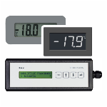
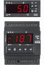
Temperature display BT 30
Offset for temperature display
Connecting BT 30 Temperature Display
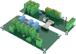
5 Installation and Startup of UA 400 E / UA 410 E
Installation
DIN rail mounting of the controller for electronic valves
Mounting on the DIN rail
Disassembling from the DIN rail
Handling of the spring terminals
Basic configuration
Setting CAN bus address
Setting controller type and master / slave mode
Terminal assignment for 230 V AC power supply
Status LEDs
Basic configuration of the controller
Naming of the controller
Restart - restart of the controller
First start / reset controller to factory settings
Maintenance and battery replacement
Firmware Update
Firmware Update requirements
Uploading the firmware update
Rectification of driver problems
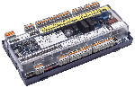
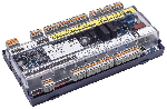
6 Pin and Terminal Assignments of UA 400 E / UA 410 E
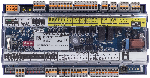
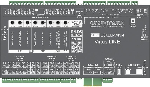
Terminal diagram
Terminal assignment of the 230 V AC power supply
Terminal assignment of the 230 V AC relay outputs
Mode of operation of the relay and transistor outputs
Terminal assignment of the 230 V AC digital inputs
Terminal assignment of the 0..10 V analogue outputs
Terminal assignment of the CAN bus
Terminal assignment of the 24 V DC transistor outputs
Terminal assignment of the DISPLAY interface
Terminal assignment of the 4..20 mA analogue inputs
Terminal assignment of the analogue inputs of temperature sensors
Sensor identification
Instructions on sensor positioning
Terminal assignment of the USB interface
Wiring of the master-slave function for defrost synchronisation
7 Operation of UA 400 E / UA 410 E
Operation possibilities
Local operation with a BT 300 x operator interface
Lock-down of the setpoint change
Remote control via a terminal
Menus and operating screens
Calling the controller menu via remote control
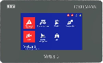
System Centre CI 4x00
Store computer CI 3x00 / operator terminal AL 300
Deactivating the input lock-down
System centre CI 4x00
Store computer CI 3x00 / operator terminal AL 300
Activating service mode
System centre CI 4x00
Store computer CI 3x00
8 Menu structure UA 400 E / UA 410 E
Contr. Type UA 121 E - Menu Tree
Menu 0 Main Menu
Menu 1 Actual Values
Menu 2 Setpoints
Menu 3 Clock
Menu 4 Messages
Menu 5 Archive
Menu 6 Configuration
Contr. Type Type UA 131 E / UA 131 E LS - Menu tree
Menu 0 Main Menu
Menu 1 Actual Values
Menu 2 Setpoints
Menu 3 Clock
Menu 4 Messages
Menu 5 Archive
Menu 6 Configuration
Contr. Type UA 141 E - Menu tree
Menu 0 Main Menu
Menu 1 Actual Values
Menu 2 Setpoints
Menu 3 Clock
Menu 4 Messages
Menu 5 Archive
Menu 6 Configuration
Contr. Type UR 141 NE - Menu tree
Menu 0 Main Menu
Menu 1 Actual Values
Menu 2 Setpoints
Menu 3 Clock
Menu 4 Messages
Menu 5 Archive
Menu 6 Configuration
Contr. Type UR 141 TE - Menu tree
Menu 0 Main Menu
Menu 1 Actual Values
Menu 2 Setpoints
Menu 3 Clock
Menu 4 Messages
Menu 5 Archive
Menu 6 Configuration
Contr. Type UK 100 E - Menu tree
Menu 0 Main Menu
Menu 1 Actual Values
Menu 2 Setpoints
Menu 3 Clock
Menu 4 Messages
Menu 5 Archive
Menu 6 Configuration
9 Decommissioning and disposal
Decommissioning / Demounting
Disposal
10 Alarms and Messages of UA 400 E / UA 410 E
Alarm signaling and monitoring
Coldroom door open alarm
High or low temperature alarm
Low temperature monitoring t0
Alarm in the event of the absence of a defrost
Alarm in the event of the minimum permitted superheat being undershot
Sensor break alarm
Suppression of sensor break alarm during defrosting
No required sensor alarm
Stall detect alarm
Implausible opening position alarm
Hardware alarm
Individual setting of priority
Termination of alarm
Alarm routes
Termination of alarm
Messages
Transient alarms and messages
Message log
11 Specifications of UA 400 E / UA 410 E
Electrical data
Mechanical data
Mechanical data of the temperature sensor L243 / 5K3A1
12 Order numbers and accessories of UA 400 E / UA 410 E
Case Controller
Components
Versions
UA 400 E / UA 410 E Betriebsanleitung - V2.00 - 27.01.2020 15:18
UA 400 E / UA 410 E Operating instruction - V2.00 - 27.01.2020 15:18
Notice d'instructions UA 400 E / UA 410 E - V2.00 - 27.01.2020 15:18
Show advanced options
Link to preview page in EDP
Link to file directly
User language settings (browser settings)
English
German
French
Newest version
:
UA 400 E / UA 410 E ­Betriebsanleitung - V2.00
:
UA 400 E / UA 410 E ­Operating instruction - V2.00
:
Notice d'instructions UA 400 E / UA 410 E - V2.00
This qr-code refers to shown link.
Read metadata
Generate preview images of pages
Generate links
Update in search index
Benachrichtigung nochmal versenden
Enter one or more users
Grant rights to a group
Prospect
Customer
Internal
Notify users about additional grants?
Send copy of notifications to me
Share
Grant access


")


