Possible causes and remedy:
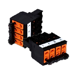
- CAN bus wired incorrectly at the male connector!
-> wire the CAN bus correctly at the male connector
(1=SHLD; 2=CAN-GND/green; 3=CAN-LOW/brown; 4=CAN-HIGH/white).
- CAN bus address selector switch at the node set to 0!
-> set the CAN bus address on the component - CAN bus address has been allocated more than once!
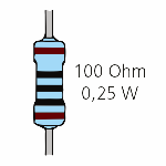
-> set unique CAN bus address on the component - CAN bus cable is not terminated with 100 Ohm at both ends!
-> terminate cable with 100 Ohm/0.25 W resistor, (see details). - CAN bus traffic is severely disrupted!
-> install Repeater. - CAN bus cable is damaged (short circuit, cable break)!
-> check cable / replace if necessary. - CAN bus voltage not OK!
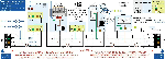
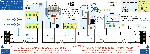
-> check the voltage level on the CAN bus with a multimeter during operation:
- between CAN-GND (terminal 2) and CAN-Low (terminal 3): 1.5 V .. 2.5 V
- between CAN-GND (terminal 2) and CAN-High (terminal 4): 2.5 V .. 3.5 V, see drawing.