Speichern
Abbrechen
Upper/lower case is ignored
Phrase search: "search this phrase"
Placeholder for one token: Techno?ogy
Placeholder for multiple tokens: EXC*
Logical operators: AND OR ....
Exclusion: cnc -tools
Defined distance: "cnc steuerung"~5
Register
Login
Deutsch
English
Favorites
...
Machine Automation
Refrigeration and Building Management Systems
/
E*LDS System
Virtus Caelum Apps
Virtus Tectum Grid
System Centre & Operator Terminal
Case Controllers
Temperature displays &
Operator interfaces
Building Management Systems
PC Software LDSWin
Receiver Module & Wireless Sensors
Gateways
Electrotechnical design
FAQ E*LDS
E*LDS explains itself
LDSWeb
E*LDS
Training
E°EDP offline archive
Discontinued Products
Pack Controllers
/
Virtus LINE VPC 5000
DISCONTINUED - VS 300
DISCONTINUED - VS 3000 Family
VS 3010 x Family
/
SIOX Extension Module
VS 3010
VS 3010 BS
VS 3015 CT
FS 3010
VS 3010 C
VS 3015 C
CE conformity declaration
VS 3010 CT
/
VS 3010 CT
Data sheet
Release notes VS 3010 CT V5.44
Handling COMBICON plug
VS 3010 CT Operating instruction
Back to document
VS 3010 CT Operating instruction
-
Overview of all pages
(1 - 192)
Page1
Page2
Page3
Page4
Page5
Page6
Page7
Page8
Page9
Page10
Page11
Page12
Page13
Page14
Page15
Page16
Page17
Page18
Page19
Page20
Page21
Page22
Page23
Page24
Page25
Page26
Page27
Page28
Page29
Page30
Page31
Page32
Page33
Page34
Page35
Page36
Page37
Page38
Page39
Page40
Page41
Page42
Page43
Page44
Page45
Page46
Page47
Page48
Page49
Page50
Page51
Page52
Page53
Page54
Page55
Page56
Page57
Page58
Page59
Page60
Page61
Page62
Page63
Page64
Page65
Page66
Page67
Page68
Page69
Page70
Page71
Page72
Page73
Page74
Page75
Page76
Page77
Page78
Page79
Page80
Page81
Page82
Page83
Page84
Page85
Page86
Page87
Page88
Page89
Page90
Page91
Page92
Page93
Page94
Page95
Page96
Page97
Page98
Page99
Page100
Page101
Page102
Page103
Page104
Page105
Page106
Page107
Page108
Page109
Page110
Page111
Page112
Page113
Page114
Page115
Page116
Page117
Page118
Page119
Page120
Page121
Page122
Page123
Page124
Page125
Page126
Page127
Page128
Page129
Page130
Page131
Page132
Page133
Page134
Page135
Page136
Page137
Page138
Page139
Page140
Page141
Page142
Page143
Page144
Page145
Page146
Page147
Page148
Page149
Page150
Page151
Page152
Page153
Page154
Page155
Page156
Page157
Page158
Page159
Page160
Page161
Page162
Page163
Page164
Page165
Page166
Page167
Page168
Page169
Page170
Page171
Page172
Page173
Page174
Page175
Page176
Page177
Page178
Page179
Page180
Page181
Page182
Page183
Page184
Page185
Page186
Page187
Page188
Page189
Page190
Page191
Page192
Upper/lower case is ignored
Phrase search: "search this phrase"
Placeholder for one token: Techno?ogy
Placeholder for multiple tokens: EXC*
Logical operators: AND OR ....
Exclusion: cnc -tools
Defined distance: "cnc steuerung"~5
Table of Contents
Conventions
Warning signs, symbols and text formatting used in this manual
Explanation of text formatting
Disclaimer in the event of non-compliance
Requirements for the personnel
Requirements for the personnel
Intended Use
Five safety rules according to DGUV Regulation 3
Electrostatic-sensitive components and control components (ESD)
ESD - Rules for handling and working
Abbreviations Used
System design VS 3010 CT
Application of VS 3010 CT
VS 3010 CT Function
Starting characteristics
First start
Restart
System Configuration
Configuration of the pressure transmitters
Low pressure transmitter Z2 (LP-Z2)
Low-pressure Regulation
Control algorithm for LP control
Control algorithm with LP step controller
Neutral zone with compressor step control
Compressor switching times for compressor step regulation
Control algorithm with LP combined control
Switching on / switching off of fixed-speed compressors
Loading / unloading of fixed-speed compressors during operation with capacity-controlled compressors Verd.
Neutral zone with compressor combined control
Compressor control times for compressor combined control
Regulation of a pack with different size compressors
Setpoint shift
Setpoint shift via room temperature
Setpoint shift - demand-dependent via consumer
Setpoint shift via CAN bus
Setpoint shift via external analogue signal
Setpoint shift via humidity sensor
Base load rotation
Base load rotation for speed controlled compressors
Load shedding
Emergency power mode
High-pressure regulation
Control algorithm for HP control
Neutral zone HP control
High pressure setpoint determination
Gas cooler outlet temperature regulation
Gas cooler control via relay outputs
Gas cooler package with ebm-papst fans
Temperature sensors for the regulation
Neutral zone fan control
Control algorithm tG with step controller
Switching times for fan motors with step controller
Fan motors - star-delta switching
Parametrisation of the switching modes
Control algorithm tG with speed control
Control algorithm tG with parallel combined control
Control algorithm tG with stage combined control
Setpoint calculation tG
Setpoint increase tG
Input signal for frequency converter
Protection of the fan motors / Fan motors base load rotation
Kickstart
Medium pressure regulation
Control algorithm for MP control
Maintaining the MP by Limiting the HP-Valve
Medium pressure compressor
Requirements
Control of the MP compressors
Monitoring of the MP compressors
Configuration of the MP compressors
Heat recovery mode
Activation of the HRC mode
HRC mode swing protection
Setpoint calculation in HRC mode
Changes to the control behaviour during HRC mode
HRC mode parametrisation
Monitoring
Safety chain
Monitoring of differential oil pressure switch / compressor high pressure limiter
Monitoring of the compressor motor overload cut-out
Cylinder head temperature monitoring
Low pressure monitoring
High pressure monitoring
High pressure monitoring too high
High pressure monitoring too low
Monitoring of the HP valve
Monitoring of the HP control error
Monitoring of the medium pressure
Medium pressure monitoring too high
Medium pressure monitoring too low
Monitoring of the MP control error
External alarm / speed controller monitoring
Condenser / fan motors monitoring
Monitoring of minimum superheat
Monitoring of the gas cooler outlet temperature
Monitoring of the switching frequency
Refrigerant monitoring
Monitoring of the fast unload / External Off
Monitoring of rupture disk / maximum refrigerant fill level
Setpoint switching
Ambient data for the setpoint switching
Consumer lockout
Spray system control
COP
COP monitoring
COP optimisation
Operating data and archiving
Operating hours of compressors and fans
Daily run times, switching pulses and switch-on rates
VS 3010 CT Installation and start-up
DIN rail mounting
Basic hardware settings
SIOX extension module - for DIN rail mounting
Connection of the SIOX modules to the pack controller
Basic settings with S1
Setting the CAN bus address with S2
Setting of the interface RS485/TTY using jumper J1
Configuration of the analogue inputs and outputs at the factory
Power supply
Status LEDs
Basic parameter settings
Start-up of speed-controlled condenser fans / compressors
Procedure for the start-up of a system
Commissioning fan control via Modbus
Battery replacement
Firmware Update
Requirements for firmware update
Update of the current firmware
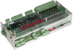
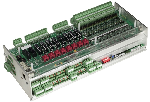
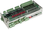
VS 3010 CT Connection and Terminal Assignment
Pin Assignments VS 3010 CT Base Module / SIOX
Terminal Diagrams for Basic Module and SIOX
Assignment for 230 V AC power supply
Assignment of the digital inputs - 230 V AC
Assignment of the relay outputs - 230 V AC
Assignment of the analogue inputs
Assignment of the analogue outputs
Assignment of CAN bus, SIOX and interfaces
Terminal assignment of the Modbus analogue module 0..10 V DC
Terminal assignment of the Modbus relay module 230 V AC
VS 3010 CT operating modes
Manual / automatic emergency mode selection
Service Mode
Display of the operating states
VS 3010 CT operation
Operation possibilities
Remote control via a terminal
Menus and operating screens
Call controller menu using remote operation
CI 4x00 System Centre - Remote control
CI 3x00 store computer / AL 300 operator terminal - remote control
Deactivating the input lock
CI 4x00 system centre - login and logout
CI 3x00 store computer / AL 300 operator terminal - unlock
Activating service mode
CI 4x00 system centre service mode
CI 3x00 store computer - service mode
VS 3010 CT menu structure
Menu tree
Main menu
Menu 1 Overview
Menu 2 Actual values
Menu 3 Setpoints
Menu 4 Hour
Menu 5 Messages
Menu 6 Operating data
Menu 7 Basic settings
Menu 8 Service mode
Decommissioning and disposal
Decommissioning / Dismantling
Disposal
Alarms and messages VS 3010 CT
Message system
Structure of the messages
Automatic Prioritisation
Overview of all alarms and messages
Technical Data VS 3010 CT
Electrical Data VS 3010 CT
Mechanical Data VS 3010 CT
Part numbers and accessories VS 3010 CT
Pack Controller VS 3010 CT / SIOX
Accessories for VS 3010 CT
Versions
VS 3010 CT Betriebsanleitung - 16.05.2023 14:34
VS 3010 CT Operating instruction
VS 3010 CT Operating instruction - 16.05.2023 14:34
VS 3010 CT Operating instruction
Show advanced options
Link to preview page in EDP
Link to file directly
User language settings (browser settings)
English
German
French
Newest version
:
VS 3010 CT Betriebsanleitung
:
VS 3010 CT Operating instruction
This qr-code refers to shown link.
Read metadata
Generate preview images of pages
Generate links
Update in search index
Benachrichtigung nochmal versenden
Enter one or more users
Grant rights to a group
Prospect
Customer
Internal
Notify users about additional grants?
Send copy of notifications to me
Share
Grant access